Click the images below to learn more about the robot and our learning experience.
About the Competition
UBC ENPH 253 Robotics Course
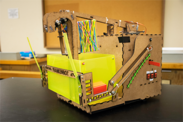
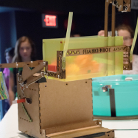
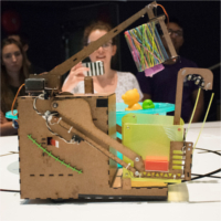
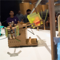
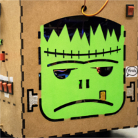
MEET FRANKENBOT!
The autonomous rescue-bot
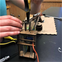
Lessons Learned
Our journey with Frankenbot
Timeline
An outline of our progress throughout Summer
June 1
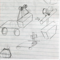
Brainstorming
We collaborated as a group to design our robot, implementing various sketching techniques to create original ideas.
June 10-12
Software Brainstorming and Organization
We divided the competition into different stages and reflected that in our software design to allow for modularity. We also determined the various functions and classes needed, and designed state diagrams for each function.
June 23
Design Proposal
Submitted a document containing a full description of our mechanical, electrical, and software systems including torque calculations, circuit diagrams, mechanical sketches and software state diagrams.
June 29
Prototyping
We began prototyping our mechanical parts, including the arm, winch, bucket and claw mechanisms.
July 4-7
Backbone Development
In preparation for tape following, we modeled the chassis, wheels, and gears in OnShape, and laser cut the parts in addition to soldering and testing QRD sensors and H-Bridge circuits. We also built the zipline bucket, soldered and optimized the IR detection circuit to detect a 1 kHz signal up to 2.5m away from the IR blaster.
July 11-14
Construction and Extremeties Development
We assembled our first chassis and began tuning PID parameters for tape following. We also built the winch mechanism that lifts the bucket to the zipline and continued the construction of the retrieval arm.
July 15-16
Software Development
We wrote the first full draft of code for each section of the competition in separate files for ease of debugging. We later combined the states into a single document once we tested each section extensively during integration.
July 21
Zipline Completion
Zipline mechanism fully complete and controlled by switches.
July 24-27
Arms and Eyes
Finished construction of retrieval arm and claw prototype. Started to integrate IR detection into the main code.
July 28
Time Trials
We showcased our progress to the instructors, demonstrating functionality in separate parts because the majority of our systems were not fully integrated.
July 31
Retrieval Arm
Solved the common ground problem with the retrieval arm, allowing for our first successful rescue of an agent.
August 1
Integration Complete
We successfully rescued six agents down the zipline for the first time!
August 2-9
Final Touches
Tuned Frankenbot’s speed and arm precision in preparation for competition.
Aug 10 Competition!
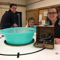
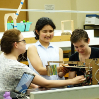
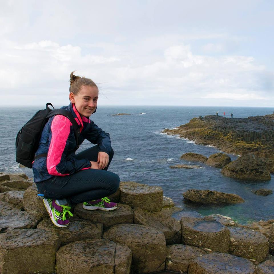
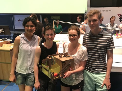
Meet our team
Adam Fink
Ashley Lloyd
Rhiannon Holmes
Rika Sugimoto
We are Engineering Physics students at the University of British Columbia. Engineering Physics is a department in the Faculty of Applied Science at UBC that seeks to provide training in both electrical and mechanical engineering along with building a strong foundation in mathematics, physics, and applied technologies.
About the Competition
UBC ENPH 253 Robotics Course
Video of Frankenbot rescuing six agents
We know that the easiest way to describe the competition might be to show a video of our robot, Frankenbot, completing the challenge. Take a look!
Description of the Competition
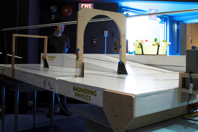
The 2017 Mission Impossibots Competition is the 17th annual robotics design course and competition held by UBC Engineering Physics. Sixteen teams of four students spent 6 weeks designing and building a fully autonomous robot that could complete the following tasks:
-Navigate an 8 x 8 ft surface by following a path of black tape that leads to six ‘captured’ agents.
-Enter the ‘lair’ when the alarm door is not armed. The door is armed in conjunction with a change in an adjacent IR blaster’s frequency. (An IR signal of 1 kHz = unarmed and a 10 kHz signal = armed.)
- Pick up six agents (bath toys) from planks situated around a 22” diameter bowl filled with water. One minute after the competition commences, the agents drop into the bowl at five second intervals.
- Once retrieved, the agents must be sent down a zipline to safety.
A full set of competition rules can be viewed here .
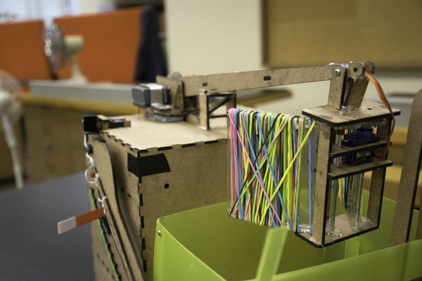
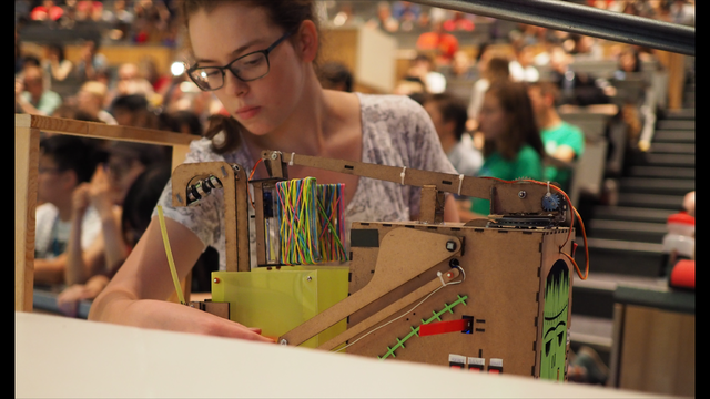
MEET FRANKENBOT!
The autonomous rescue-bot
Frankenbot’s Progress throughout the summer
Here is a cute video we made of Frankenbot’s growth and the fun summer we had building him!
Tools and Materials used to build Frankenbot
TINAH Resources The TINAH microcontroller board executed the software we uploaded and was the “brain” of Frankenbot
- 8 Analog Inputs
- 16 Digital Inputs
- 4 PWM outputs for DC motors
- 4 PWM outputs for servo motors
Electrical Our entire electrical system was designed and soldered on PCBs
- Lithium-Polymer batteries (1 x 16V, 2 x 8V)
- Soldering irons
- PCBs
- Simple discrete and active components
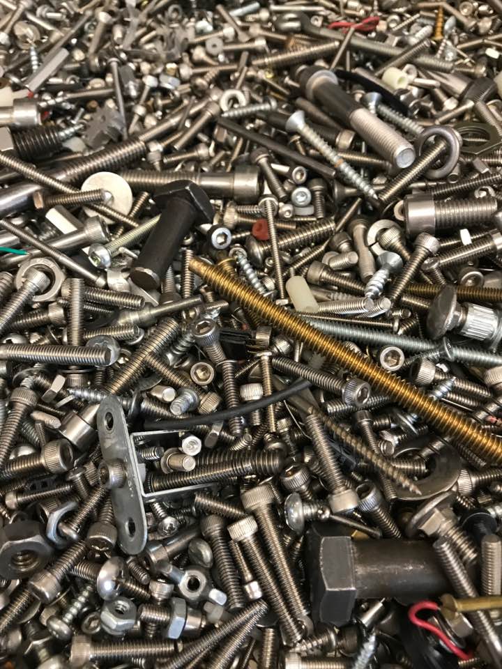
Mechanical All of our mechanical parts were designed in OnShape cloud CAD software and prototyped using the materials available.
- Long rods (Aluminum, Steel, etc.)
- Nuts, bolts, etc.
- Various materials (delrin, acrylic, polypropylene, etc.)
- OnShape software
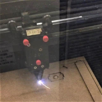
Prototyping Tools We received training on proper use of all the prototyping tools below
Detecting and following black tape was essential for navigating the
competition surface,
from the start line up the ramp and around the water tank.
How we did it
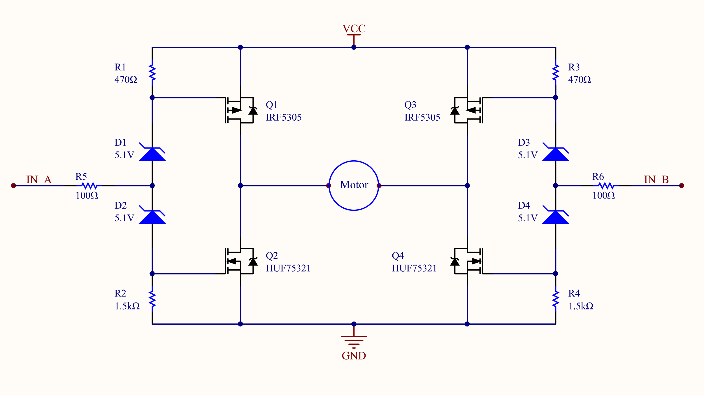
The drive system consists of two DC motors connected to gears that rotate the wheels around an axle.
Rubber tires (not shown) were used to increase friction, facilitating sharp turns and steep climbs.
The DC motors were controlled by the TINAH board through an H-bridge circuit (below: Source: ENPH 253 Project Lab Page) so that we could drive at high power.
To detect the black tape, we used QRD reflective sensors that read a low voltage on
highly reflective surfaces, thereby allowing us to distinguish between the white surface and black tape.
Frankenbot has three pairs of QRDs: one pair in the middle
for tape following up to the tank, and two pairs on either side of the robot
used for tape following around the tank.
The two additional pairs of QRDs helped better position the robot around the tank to facilitate
rescuing the agents on the platforms.
A software-based PID (proportional-integral-derivative) control was used for navigation along the tape.
The PID was tuned through extensive testing, from which we found that the effects of
integral and derivative control were negligible for this simple system.
Main challenges
Traveling around the tank proved to be the biggest challenge due to the short segments of extra tape
that marked the plank positions. To minimize the risk of the robot traveling down the tape,
we tuned a speed bias for each wheel so that if the robot was on black tape, it would travel in a circular path rather than a straight line.
The QRDs also proved to be very sensitive to the positioning, so we had to secure them at their optimal
heights above the ground using twisted O-Rings and a glue gun.
Navigate safely through the Armed Door
The second door from the startline is an alarm door to prevent intruders from
entering the compound. Frankenbot has to determine whether the door is armed or unarmed
based on the IR signal being emitted from the door (10 kHz indicates armed, 1 kHz indicates unarmed).
How we did it
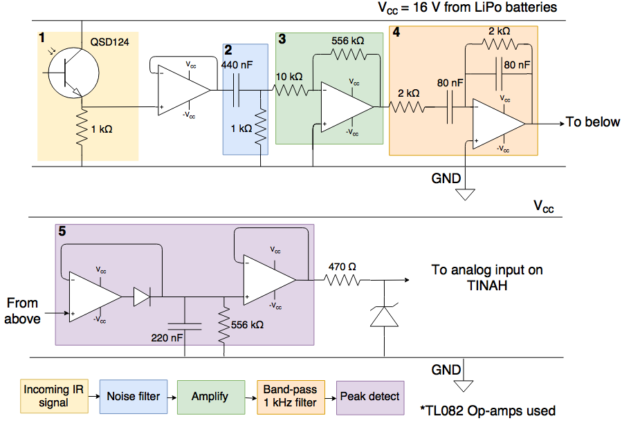
Frankenbot’s 1kHz IR detector is composed of a phototransistor, high and band-pass filters, amplifiers,
and a peak detector.
The phototransistor was installed at the front of the robot, underneath the bucket,
to ensure that no part of the robot is blocking the detector.
Below is a diagram of our IR amplification and filtration circuit designed to detect a 1kHz signal.
The band-pass filter was tuned to allow 1 kHz signals to pass through, producing a detector with a
high voltage output for 1 kHz and a low output for 10 kHz.
The gain of the amplifier was adjusted to increase the sensitivity of the detector even from a
distance, while ensuring that the voltage difference between 10 kHz and 1 kHz is significant.
We succeeded in making a detector that would switch from an output of 0.6V at 10 kHz
to 5.0V at 1kHz. Frankenbot could detect the IR frequency change from a maximum distance of 2.5m and a minimum distance of 0.2m.
Main challenges
The IR levels in the room were affected by the lighting, especially sunlight
since the intensity of the sunlight would change throughout the day.
We addressed this issue by testing and tuning the threshold for the IR detector in
the competition room in advance.
The position of the robot on the competition surface also affected the output from the
IR detector significantly, as the angle of the phototransistor relative to the signal changed
and the doors also blocked the signal. To reduce the variation in IR signals detected,
we decided to program Frankenbot so that he stops right after the first door
(which he detects with the red-coloured collision switches on the side of the chassis)
before detecting the IR signal and making the decision to wait or drive through.
Rescue Agents out of Water Tank
The agents are captured in a water tank! Frankenbot has to rescue them out of the tank
before they drown!
How we did it
Frankenbot has three servo motors controlling the retrieval arm and claw:
a turning servo for the left-to-right rotation of the arm, under a turntable;
a lifting servo for the up-and-down motion;
and a claw servo for the opening and closing of the claw.
The claw has been decorated with rubber bands that help securely grip the agents
with friction and by molding to the shape of the agents.
Main Challenges
Initially, we had the servo motors directly connected to the TINAH board,
only to realize that the TINAH was not able to supply enough current to all three motors.
Because of this, we prepared voltage regulators for each servo motor, powered directly from the LiPo batteries.
However, even after powering the servo motors with regulators, the arm and claw continued to
flutter and would not stay still. After consulting an instructor, we learned that
the problem was caused by a lack of a common ground between the power supply (battery)
and the PWM signals (from the TINAH microcontroller) fed to the servos. Adding a common ground connection
between the two helped stabilize the arm and claw, and that same day Frankenbot was able to rescue
his first agent from the tank.
Another major issue with the arm design was the enormous strain forced on the lifting servo.
Reducing the torque on the servo with a larger gear ratio was not enough to
alleviate the strain, so a platform was built to help hold the arm in its resting position when not being used.
Still, it was evident that the servo motor was fatigued when used continuously.
If we were to rebuild the robot, we would redesign the retrieval arm by installing a spring under the arm
to counter the weight of the claw, shortening the arm, or reducing weight at the end of the arm, the claw.
Plank Detection
How we did it
Frankenbot has collision switches with a red polypropylene extension on each side
to tap the servo motors that are located around the tank
(these servos control the platforms and are responsible for drowning the agents
by dropping them into the water).
The length of the polypropylene “bumpers” were tuned by testing how close the robot chassis was
from the tank and servos, and trimmed as needed.
Main Challenges
The plank detectors were sensitive to any physical change, such as the servo motor mounts being flattened
against the tank or the robot’s turn radius being increased or decreased.
Tuning the robot’s turn radius was important to ensure that Frankenbot knew
which plank he was passing at any given point in time.
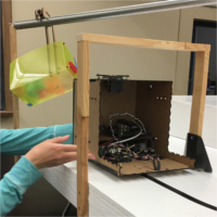
Send Agents Down the Zipline
Once rescued from the tank, the six agents had to be freed from captivity
by traveling down a metal rod known as the zipline.
Bucket
How we did it
Frankenbot has a yellow polypropylene bucket in which he places the agents as
he rescues them out of the water tank. This bucket has a hook with ball bearings
around a hollow aluminum rod, helping the bucket roll smoothly down the zipline.
O-rings were used to hold the ball bearings in place.
Frankenbot lifts the bucket onto the zipline using a winch mechanism consisting of a DC motor
powered through an H-bridge circuit, and a winch that is fastened to a rotating square shaft
connected to the lifter arms.
To detect the zipline, Frankenbot uses the two yellow polypropylene flaps
at the end of the lifter arms, with a collision switch behind each.
Frankenbot corrects his orientation relative to the zipline using these switches.
Main Challenges
The initial torque calculations were done on a winch that had a 20% smaller diameter,
so the first lifter prototype caused too much strain on the DC motor, which could only lift
a maximum of four agents. We attempted to increase the diameter of the winch,
but this was limited by the arm that would rotate right above the winch
and by the overall height restriction of the robot. In the end, we were able to
lighten the load on the winch by exchanging the solid steel rod on the bucket hook with
a hollow aluminum rod, thereby reducing the weight.
Lessons Learned
Our journey with Frankenbot
“If you want to go fast, go alone. If you want to go far, go together”
Teamwork
It is arguable that one of the most important lessons we learned was how to work as a team! We were respectful and understanding of one another, carefully considered each other’s input and incorporated fun into team building activities!
Communication
We also learned that communication is incredibly important. We found that constant communication about progress and part development led to a well informed team. We were able to help each other debug since we already knew the status of each concurrent task. We also found it incredibly valuable to communicate effectively with the instructors and TAs. When we were able to explain our designs and difficulties in such a way that people external to our team could understand, we saw that we received much more helpful advice. We also recognize that our instructors and TAs have much more experience than our team combined so we were very open to feedback. Our willingness to learn from our mentors played a huge role in our success.
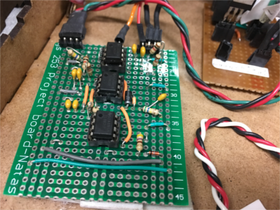
Electrical
Messy wirings = headaches later
Connection Troubles
Connections are so important. Ensuring that all of our PCBs passed continuity checks and had proper connections probably saved us hours debugging. Unfortunately we learned the hard way that we should have done this for all connections, including wires and cables connecting between the TINAH microcontroller and PCBs. Insecure connections between connecting cables was the root of many of our electrical problems and we wish we had soldered reliable connections earlier on.
Facilitating the Debugging process early on
When soldering PCBs, we made sure that we followed a colour code for wirings and used the same power rail system. This helped us tremendously because all of us could understand the circuits at a moment’s glance. This meant that we didn’t need to wait for the person who initially designed the circuit to debug it if we ran into problems. We felt it was good practice to leave our circuits tidy enough so that anyone could step in at a moment’s notice and have minimal trouble transferring roles.
Since we were relatively inexperienced going into this course, we had limited debugging experience. Throughout the summer, however, we developed many techniques for debugging circuits in a timely manner.
Tips and Lessons Learned:
-First, check continuity between all wirings - Use a DMM to check power for all critical PCBs. Is ground grounded? Is 16V, 16V? - Is there a common ground connected between the microcontroller and PCBs? - Are all of the components still functional? Transistors? Op Amps?
Mechanical
Simple is best
We appreciated how easy our chassis was to assemble. The different faces of the chassis snapped together in a tight, secure binding. Although the chassis was strong, it was also easy enough to remove one of the faces and access the circuits beneath. This is something that we are proud of. Unfortunately, we recognize that our winch and arm mechanisms were not as simple to assemble. Both mechanisms took up to an hour to assemble from scratch whereas the chassis took about three minutes. Granted, the arm and winch mechanisms had more components than the chassis, but we recognize that we could have made it simpler. This is something we will keep in mind in future years.
Prototyping and Integration
We learned that you can never prototype too early. Although we went through several iterations of our winch and arm mechanisms, we recognize that it is easy to overlook small details that an OnShape or SolidWorks model might miss.
Although we were warned, we were astonished to see how easily the modification of a component in one area of the robot often affects another system that is seemingly unrelated. To combat this we made sure we integrated each component separately so that we could isolate problems and debug faster.
Tips and Lessons Learned:
-Simple designs are always better than complicated designs - Easy to assemble mechanisms will save you later - Prototype often and as early as possible - Integrate components one at a time to isolate problems
Software
Readable code saves hours later
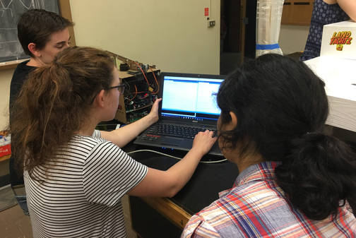
Testing and Debugging
We tested our software in very small chunks. We would test each addition to the software extensively before adding the next sections. We also divided each section of the competition into different ‘states’. Our use of modular code was very effective since it made testing and debugging simpler. We also emphasized the importance of readable code to ensure that all team members could understand it easily and start editing at a moment’s notice.
We also attribute a lot of our software success to the use of hardware when debugging. We used the microcontroller’s digital LCD display to print statements so that we knew what Frankenbot was trying to do at all times. In addition, we used a buzzer to send a loud ‘beep’ at critical points in our code. This helped us rule out problems and find the core problems faster.
Four Software Experts
All four of us were heavily involved in the software development. This was an asset since all of us could make adjustments when needed. We also appreciated this when debugging since we each caught different bugs in the code.
Tips and Lessons Learned:
-Create modules to isolate tasks and bugs -Write readable code so that others can understand -The more eyes searching for bugs, the better - Test code in small pieces
Competition
Although Frankenbot was completing the challenge very quickly and reliably before competition, he didn’t perform as well the day of competition. The week leading up to the competition, Frankenbot would rescue all of the agents and send them down the zipline 95% of the time. He was also relatively quick, completing the course in 50-60 seconds.
At the start of the competition, Frankenbot won both face-offs in round robin. Because of this, Frankenbot was sent to the elimination rounds. During the quarterfinals, however, Frankenbot’s grip around one agent slipped. Since Frankenbot rescued five agents and our opponent rescued six, we were eliminated.
Losing in the quarterfinals was a great learning experience for us because we realized that reliability is imperative. Even though Frankenbot was consistent before the competition, his components were fatigued by the time competition day came and his arm was not as reliable as it once was. Now we understand the value of resilient parts and designing for wear and tear. We know that if our servo motors on Frankenbot’s arm hadn’t been under so much strain, we might have had more success.
Thank you
Regardless, we had a very fun time building Frankenbot. We want to thank our professors Andre Marziali, Jon Nakane and Bernhard Zender for their guidance throughout the summer. We would also like to thank our patient TAs, Connor Shannon, Reily Blackner and Connor Haberl. Thanks for the fun summer!